Simulation
The Simulation workspace (Ctrl+3) sets up and runs analyses of the active cell’s
schematic and shows the results.
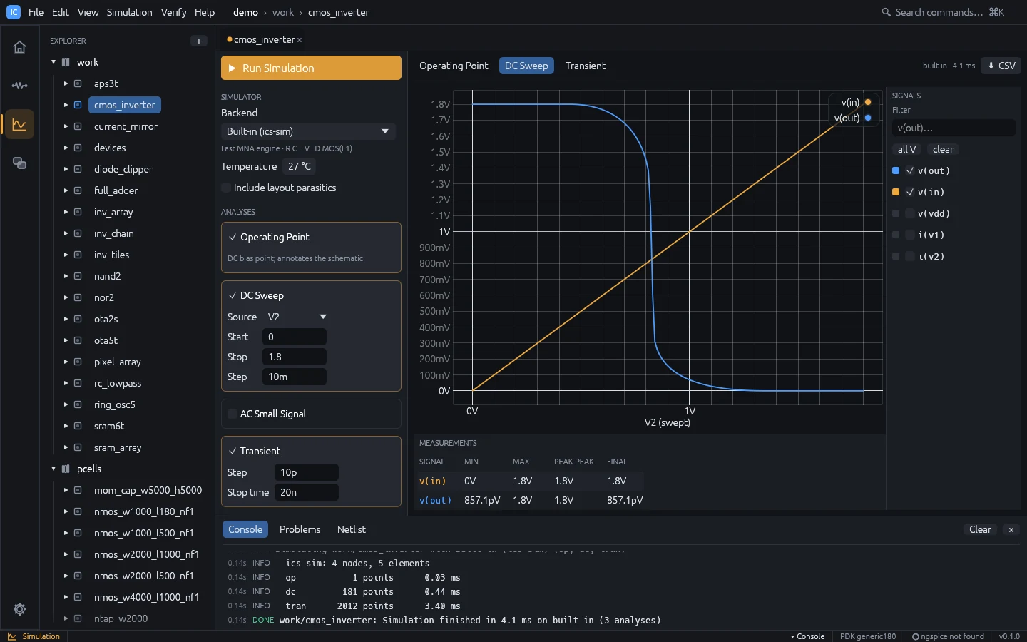
Running a simulation
- Open a cell with a schematic and switch to the Simulation workspace.
- In Analyses, tick the analyses to run and fill in their fields.
- Press Run Simulation,
F5orCtrl+Enter(also Simulation > Run or Simulate in the schematic toolbar).
Simulation runs in the background. Starting it from another workspace switches to the Simulation workspace. Errors appear in a red Simulation error box and in the console.
Setup panel
Simulator
| Field | Meaning |
|---|---|
| Backend | Built-in (ics-sim) (default), ngspice, or Auto (built-in, ngspice when needed) (see Backends) |
| Corner | Model corner of the PDK model library; shown only when the technology’s models have corners (default: the library’s default corner) |
| Temperature | -55 to 200 °C, default 27 (written as .temp); the built-in engine scales its models with it |
| Include layout parasitics | Add parasitics extracted from the cell’s layout (see below); disabled when the cell has no layout |
The line under the backend shows whether ngspice was found, or that PDK models need ngspice when the technology has a model library. With Auto it shows which ngspice the engine would switch to. Set the ngspice path in Settings (see Installation).
Analyses
| Analysis | Fields (defaults) | Notes |
|---|---|---|
| Operating Point | none (on by default) | Annotates the schematic |
| DC Sweep | Source, Start 0, Stop 1.8, Step 10m | Source is any V or I source in the schematic |
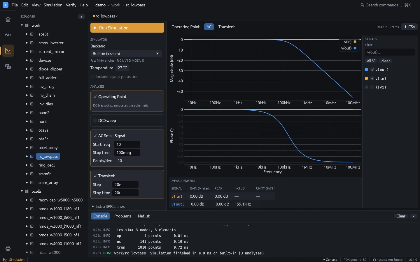
| AC Small-Signal | Start freq 1, Stop freq 10g, Points/dec 20 | Decade sweep; give a source an AC magnitude |
| Transient | Step 10p, Stop time 20n | Give a source a Transient waveform |
| Noise | Output node out, Input source, Start freq 1, Stop freq 1g, Points/dec 10 | Written as .noise v(out) <source> dec ...; the input source is picked from the schematic’s sources |
Fields with an invalid value turn red; validation messages appear under the card.
Extra SPICE lines
Lines in this collapsible section are appended verbatim to the deck before the analyses,
for example .options reltol=1e-4. Show netlist displays the generated deck next to the
results.
The setup (backend, corner, analyses, temperature, parasitics flag, extra lines and the
sweep setup) is saved per cell in sim.json.
Results
Each analysis has its own tab: Operating Point, DC Sweep, AC, Transient,
Noise.
The tab bar shows the backend and run time, and CSV exports the current dataset (AC
values as name_re / name_im columns).
Waveforms
- Signals (right): tick signals to plot. Filter narrows the list, all V selects
every node voltage, clear clears the selection. By default
v(out),v(in),v(vout)andv(vin)are shown when present, otherwise the first three voltages. The selection is kept per analysis between runs. Waveforms plotted from the Waveform Calculator appear here as signals named after their expression. - Compare runs (above the signal list): the earlier runs of the cell. Tick one to draw its signals dashed on the same plot and list them in the measurements (see Results Browser).
- Plot: DC and transient results share one plot. AC results are a Bode pair: Magnitude (dB) over Phase (°) on a logarithmic frequency axis, with linked zoom and cursor. Hover a trace to read values. Scroll to zoom, drag to pan, double-click to reset.
- Noise: the output noise density
onoise_spectrumand the input-referred densityinoise_spectrum(V/√Hz) on logarithmic axes. The built-in engine computes them from resistor and MOS channel thermal noise, diode shot noise andkf/afflicker noise, and writes the integrated output noise (V rms over the sweep) to the log. - Measurements (bottom), one row per plotted signal:
- DC and transient: MIN, MAX, PEAK-PEAK, FINAL.
- AC: GAIN @ fstart, PEAK, f -3 dB, UNITY GAIN f.
Operating point
The Operating Point tab lists node voltages and branch currents, and per device:
- MOS: region (cutoff, saturation, triode),
id,vgs,vds,vth,gm,gds - diode:
vd,id,gd - resistor:
v,i,p
Device details come from the built-in engine only. The node voltages are also drawn on the schematic (see Schematic).
Example: transient of the RC low-pass
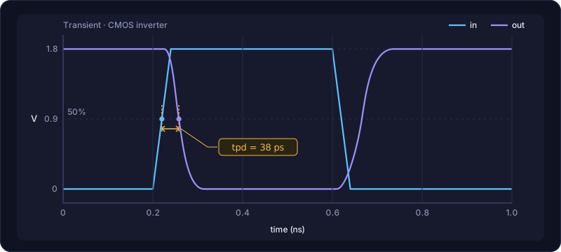
- Run
ic-studio --demo --cell rc_lowpass --workspace simulation. - The cell has Operating Point, AC and Transient set up. Press
F5. - Open the AC tab: the f -3 dB column shows about 159 kHz for
v(out). - Open the Transient tab to see the input pulse and the filtered output.
- To change the input, go to the schematic (
Ctrl+2), select the source, edit Transient, and pressF5again.
Measurements, corners and Monte Carlo
- Tools > Waveform Calculator evaluates expressions on the results, such as
bandwidth(v(out)/v(in)),risetime(v(out))orphasemargin(v(out)), and plots derived waveforms. See Waveform Calculator. - Tools > Corner / Sweep Manager runs the setup over model corners, temperatures and parameter values, and Monte Carlo variations, in parallel; specs with limits are checked on every point, with statistics, yield, overlaid waveforms and an HTML datasheet. See Corner / Sweep Manager.
- Tools > Results Browser keeps earlier runs for comparison, for example the schematic against the post-layout simulation.
The Sweep…, Monte Carlo… and Optimizer… buttons at the top of the setup panel open these tools for the active cell.
Monte Carlo window
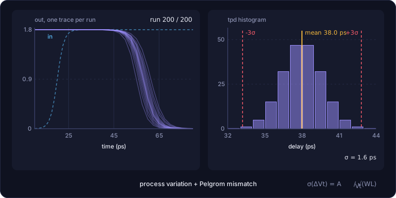
Simulation > Monte Carlo… (also in the Tools menu and the command palette) runs the cell’s setup many times on the built-in engine with random device variation, and shows statistics of calculator measurements. Every run draws:
- a process shift shared by all MOS devices of one polarity: threshold (Vto sigma,
V, default
20m) and relative transconductance (kp sigma, default0.03); - a per-device mismatch scaled by gate area (Pelgrom): σ(ΔVth) = Avt / √(W L) and
σ(Δβ/β) = Abeta / √(W L), with Avt default
5n(5 mV·µm) and Abeta default10n(1 %·µm).
- Set Runs (default 100) and Seed (runs are reproducible for a seed).
- Add a measurement with + Measurement: an analysis (
op,dc,ac,tran,noise) and a calculator expression with a scalar result, such asop: v(out)orac: bandwidth(v(out)). - Press Run. A progress bar counts the samples; Stop ends the run after the current sample and keeps the results so far.
- The table lists n, mean, sigma, min, max and the failed runs of every measurement; select one to see its histogram.
The setup is saved with the cell (sim.json). Monte Carlo varies the built-in engine’s
models, so a deck that loads a PDK model library is rejected: use the PDK’s own statistical
corners with ngspice instead. The Corner / Sweep Manager has a
separate Monte Carlo of instance parameters and design variables on any backend. From the
command line: ics mc <project> <cell> --measure op:v(out) (see
Command line).
Post-layout simulation
When Include layout parasitics is ticked and the cell has a layout, IC Studio extracts the layout, matches its nets to the schematic through LVS and adds to the deck:
- wire capacitance to substrate (
Cpar_*), - lateral and overlap coupling capacitance between nets (
Cc_*), - MOS drain / source junction sizes (
ad as pd ps) from the drawn diffusion, - an RC network of wire, via and gate resistance (
Rpar_*), with each MOS terminal moved to the nearest node of its net, - layout-dependent effect parameters for PDK models whose model library sets
lde = true(SKY130 does; see Technology): the finger countnfof each MOS and, for straight gates on rectangular diffusion, the gate-to-diffusion-edge distancessa/sband the gate spacingsd, for BSIM4 stress models. Withoutldethese are left out.
Coupling to a layout net with no schematic counterpart is lumped to ground. The console
shows a one-line summary. For a useful result, the layout should be LVS clean (see
Verification). From the command line: ics sim <project> <cell> --parasitics.
Backends
Built-in engine
A modified nodal analysis engine written in Rust. It supports:
- elements
R C L V I D M(no subcircuits or behavioural sources), - sources:
DC,AC mag [phase],PULSE(v1 v2 td tr tf pw per),SIN(vo va freq td theta),PWL(t v ...), - directives
.model,.op,.dc,.ac,.tran,.noise,.temp,.title,.end; other dot lines such as.options,.paramand.subcktare ignored, and a deck with.includeor.libis rejected (model libraries need ngspice), - diode model:
is n cjo vj m fc tt rs bv ibv kf af eg xti tnom, - MOS level 1:
vto kp u0 lambda gamma phi tox ld cgso cgdo cgbo cj cjsw mj mjsw pb fc is js rd rs rsh kf af tnom, with instance parametersw l m ad as pd ps nrd nrs.
The models follow SPICE level 1 and the SPICE diode:
- Capacitances depend on bias. MOS gate capacitance follows the Meyer model per region
(accumulation, depletion, triode, saturation) when
toxis given; junction and diode depletion capacitances followcj,mj,pb,fcand the sidewall terms. Transient analysis integrates charge, so it is conserved. - Parasitic resistances: MOS
rd/rs(orrshwithnrd/nrs) and diodersadd internal nodes; MOS bulk junctions are modelled as diodes. - Temperature: MOS
kp,phi,vtoand the bulk junctions, and diodeis(witheg,xti),vjandcjoscale fromtnomto the analysis temperature. - Transient step control: steps are accepted and sized by a local truncation error estimate, so fast edges are resolved even with a coarse Step.
The generic nmos / pmos models the netlister writes use vto = ±0.45 and
kp = 280u / 70u with tox = 4n. A MOS parameter left out takes its SPICE default
(vto = 0, kp = 2e-5, or u0 · cox when tox is given; no intrinsic gate capacitance
without tox).
What the built-in engine approximates
The engine reports what it does not evaluate as written: a MOS level other than 1
(evaluated as level 1), model and instance parameters it ignores, and dot lines it skips.
The warnings appear in the console log, in the status line of the run (the first one,
with a count of the rest), in ics sim / ics spice output and in the MCP simulate
result. Check them before trusting a built-in result of a foreign deck.
Auto
Auto runs the built-in engine when it evaluates the deck as written, and switches to
ngspice when it would not: the deck loads model libraries (.lib, .include) or compiled
Verilog-A models, or the engine would warn about the deck (see above). The reason is
reported as a warning, for example auto: ngspice, because the deck loads external models (...). Without ngspice installed it stays on the built-in engine and says so.
ngspice
With the ngspice backend, IC Studio runs ngspice in batch mode and reads its raw output.
ngspice reads the deck itself, so subcircuit devices (X), .include and .lib model
libraries of a PDK work; IC Studio only takes the analyses (.op, .dc, .ac, .tran)
from the deck when the setup lists none.
A PDK model library can list compiled Verilog-A models (osdi = [...] in the PDK file’s
[models]), which ngspice loads with pre_osdi before the deck; the IHP SG13G2 PDK file
uses this for its PSP 103 models.
Built-in engine versus ngspice
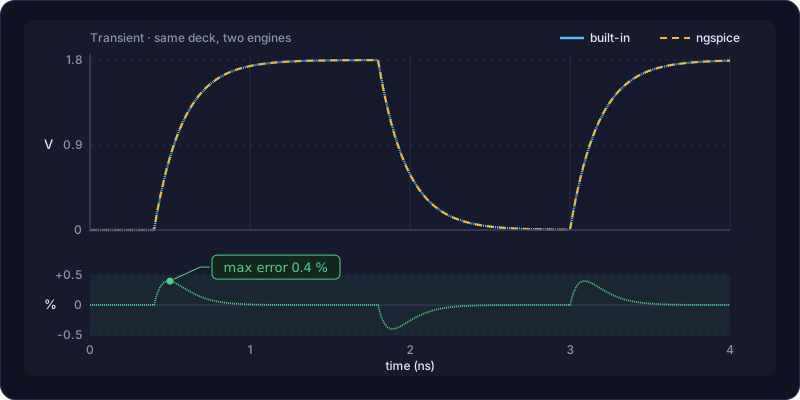
--compare on ics sim and ics spice runs the deck on both engines and prints, per
vector, the worst disagreement: the largest absolute error (complex magnitude for AC), the
error relative to the largest magnitude of the ngspice vector, and where on the sweep or
time axis it occurs. The test results are interpolated onto the ngspice scale; transients
are read up to half a step either side, so an edge that lands a step earlier is not
counted as a model error. The command exits with 1 when the worst relative error exceeds
--tol (default 0.05).
ics sim demo cmos_inverter --compare --tol 0.02
ics spice deck.cir --compare
The repository’s golden correlation suite (cargo test -p ics-sim --test correlation)
compares a set of decks the same way when ngspice is available; ICS_NGSPICE sets the
ngspice executable (it also becomes the default ngspice path of the app and the CLI).