Circuits in ten minutes
Chip design rests on a few ideas from basic electronics. This chapter covers just those, with an example you can simulate at the end.
Voltage, current and resistance
- Voltage (V, volts) is the electrical “pressure” between two points. It is always measured between two nodes; when only one node is named, the other is ground (0 V).
- Current (I, amperes) is the flow of charge through a wire or device. Chips work with milliamps (mA, 10⁻³ A), microamps (µA, 10⁻⁶ A) and less.
- Resistance (R, ohms Ω) is how hard a device resists current.
They are tied together by Ohm’s law:
V = I · R 1 V across 1 kΩ drives 1 mA
A resistor turns electrical energy into heat. The power it burns is P = V · I. Power
is why chips get warm, and why designers care about every microamp.
Kirchhoff’s laws: how circuits are solved
Two rules are enough to solve any circuit, and they are exactly what a SPICE simulator does:
- Current law (KCL): the currents into a node add up to zero. What flows in, flows out.
- Voltage law (KVL): the voltages around any closed loop add up to zero.
A simulator writes one KCL equation per node, with each device’s current as a function of its node voltages, and solves the whole set at once. This is called modified nodal analysis, and it is what the built-in engine of IC Studio does.
Nodes, nets and ground
In a schematic, every set of connected wires is one net (or node). Nets get names
(in, out, vdd) or automatic names (net1). The ground net is called 0 in SPICE.
Every circuit needs a ground: it is the reference all voltages are measured from.
The supply (vdd) is the net that feeds power to the circuit. In the generic
technology it is 1.8 V.
Capacitors and the RC time constant
A capacitor (C, farads F) stores charge: Q = C · V. It is two conductors separated
by an insulator. On a chip, capacitors are everywhere, whether you want them or not:
every gate of a transistor is a small capacitor, and every wire has capacitance to the
substrate and to its neighbours. Values are tiny: femtofarads (fF, 10⁻¹⁵ F) to picofarads
(pF, 10⁻¹² F).
The voltage on a capacitor cannot jump; it takes time to charge through a resistance. Charging C through R, the voltage follows an exponential with the time constant:
τ = R · C 1 kΩ · 1 nF = 1 µs
After one τ the capacitor has reached 63 % of the final voltage, after 3τ 95 %, after 5τ 99 %.
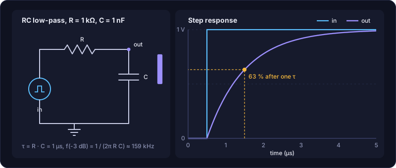
Why this matters for chips: a logic gate driving the next gate is a resistor (the transistor that is on) charging a capacitor (the next gate plus the wire). The RC product sets how fast a chip can run. Almost every speed question in digital design comes back to “how big is R, and how big is C?”
Frequency response, decibels and Bode plots
The same RC circuit behaves differently for slow and fast signals. A slow sine wave passes through; a fast one is shorted to ground by the capacitor before it can charge. It is a low-pass filter with a corner (−3 dB) frequency:
f(-3 dB) = 1 / (2π · R · C) 1 kΩ, 1 nF → 159 kHz
The ratio of output to input amplitude is the gain, usually in decibels:
| Gain (ratio) | Gain (dB) = 20 · log₁₀(ratio) |
|---|---|
| 100 | 40 dB |
| 10 | 20 dB |
| 2 | 6 dB |
| 1 | 0 dB |
| 0.707 | −3 dB (the “corner”: half the power) |
| 0.1 | −20 dB |
A Bode plot draws gain in dB and phase in degrees against a logarithmic frequency axis. Above its corner, an RC filter loses 20 dB per decade (a factor of 10 in frequency). AC analysis in a simulator computes exactly this plot.
The three main analyses
| Analysis | Question it answers | Example |
|---|---|---|
| Operating point (OP) | What are the DC voltages and currents with the inputs held still? | Is every transistor biased correctly? |
| DC sweep | How does a DC output change as one source is swept? | An inverter’s transfer curve |
| AC (small-signal) | How do small sine waves pass through, at each frequency? | An amplifier’s gain and bandwidth |
| Transient | What happens over time with real waveforms? | A gate’s delay, an oscillator’s period |
Reading a SPICE netlist
Underneath every schematic is a netlist: one line per device, listing its nodes and its value. IC Studio shows it in the Netlist tab of the bottom panel. The RC filter:
* RC low-pass
V1 in 0 DC 0 AC 1 PULSE(0 1 0.5u 1n 1n 10u 20u)   ; source between in and ground
R1 in out 1k                                      ; 1 kΩ from in to out
C1 out 0 1n                                       ; 1 nF from out to ground
.ac dec 20 1 10meg                                ; AC: 20 points per decade
.tran 10n 5u                                      ; transient: 5 µs
.end
- The first letter is the device type:
Rresistor,Ccapacitor,Vvoltage source,MMOSFET,Ddiode. - Then the nodes it connects, then the value.
- Values use SPICE suffixes:
f10⁻¹⁵,p10⁻¹²,n10⁻⁹,u10⁻⁶,m10⁻³,k10³,meg10⁶,g10⁹. Careful:mis milli, so a megohm is1meg. - Lines starting with
.are commands: models, analyses, options.
Try it: open the demo’s rc_lowpass:
ic-studio --demo --cell rc_lowpass --workspace simulation
Press F5. On the AC tab, the f -3 dB column shows about 159 kHz. On the
Transient tab you see the exponential charging. Then go to the schematic (Ctrl+2),
change R1 to 2k in the inspector and press F5 again. Before you look: what will the
corner frequency be?1
1 Doubling R doubles τ and halves the corner: about 80 kHz.
Next: The MOSFET, the device the rest of the course is built on.